

The Ultimate Guide to Architectural Floor Plans: Master the Spatial Blueprint
Think about it.
You walk into a building and immediately feel an unexplainable sense of calm and luxury. The rooms flow seamlessly, the transitions feel natural, and there is zero layout chaos.
Ever wonder why?
It is not an accident. It is the result of a meticulously executed architectural breakdown.
But here is the catch: trying to bring a space to life without understanding its true anatomical makeup is an absolute trap. You risk bleeding cash on structural errors, creating unusable dead zones, and suffering massive building regret.
In this guide, we will explore meticulously how professional floor plans are structurally engineered from scratch. Plus, to make things simple, we will break down the easiest, high-tech floor plan maker tools available to help you instantly map out your own ideas with zero drafting friction.
Want to pull back the curtain on true spatial engineering?
Let's dive right in.
What a Floor Plan Is: The Master Visual Contract
Let’s look at the facts.
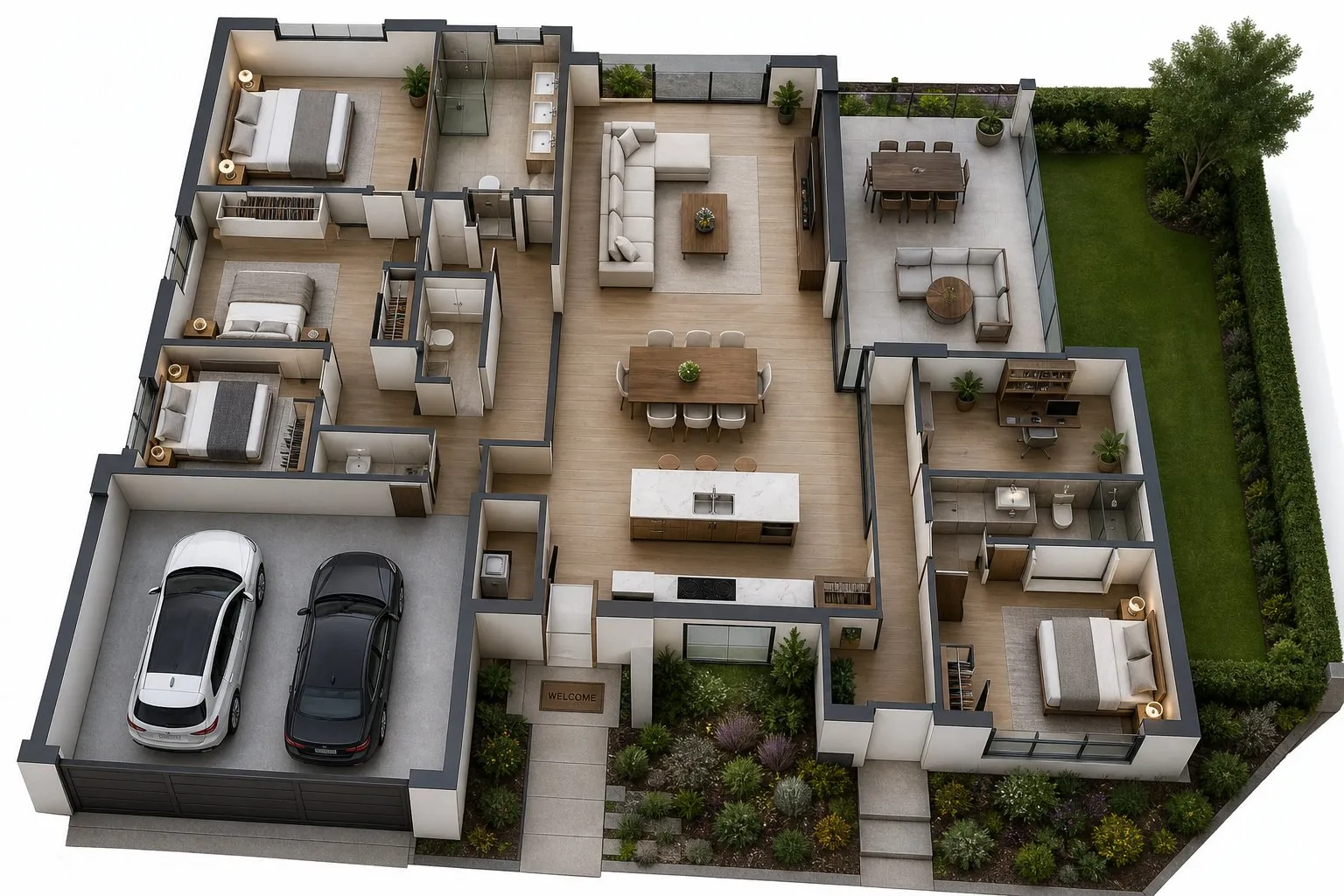
At its baseline level, a floor plan is a scaled diagram of a room or building viewed from above. It acts as the definitive visual map of physical space, detailing the explicit relationships between rooms, traffic flows, door placements, and window openings.
But it is far more than a simple sketch.
It is a highly technical communication framework. It strips away complex visual clutter to show you exactly how a structure functions horizontally, serving as the absolute foundation for every single step of design, estimation, and construction. Using a premium floor plan design layout eliminates all structural confusion before builders even step onto the site.
The Technical Meaning of a Horizontal Building Slice
Here is what most people miss.
A true layout map is not just an arbitrary overhead drawing. Technically speaking, it is a two-dimensional horizontal building slice.
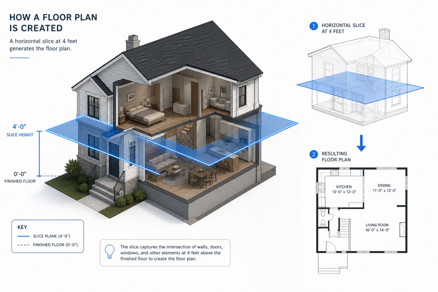
Imagine taking a massive, surgically precise laser and cutting a building completely in half along a horizontal plane parallel to the earth. If you lift the entire roof and upper structure away, then stand directly above the exposed remaining space looking straight down, you are looking at a floor plan. This explicit perspective reveals the precise thickness of exterior boundaries, the exact placement of interior partition walls, and the structural voids that form the backbone of the property.
Why the 4-Foot (1.2-Meter) Horizontal Cut Height Is Standard
You might be wondering: where exactly does that horizontal slice happen?
In global industry standard architecture drafting rules, the cut plane is placed precisely at 4 feet (1.2 meters) above the finished floor level.
Why this specific height?
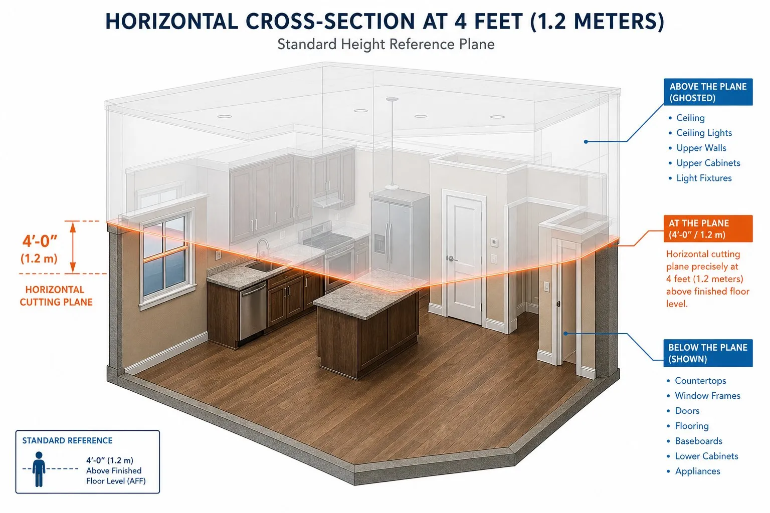
Because it is the ultimate sweet spot for capturing human-scale data. If you cut too low (say, at 1 foot), you slice beneath the windows and completely miss their locations. If you cut too high (say, at 8 feet), you pass clean over the doors and entryways. By fixing the laser slice at exactly 4 feet, the plan cleanly cuts right through the center of standard windows, main entryways, structural columns, and interior doors. This unlocks complete spatial clarity, capturing every crucial opening that controls the light, safety, and flow of the environment.
Floor Plans vs. Blueprints: The Main Differences
Let's clear up a major piece of industry confusion.
People often use the terms floor plan and blueprint interchangeably. But that is a critical mistake.
To break it down simply: a floor plan is a single, specific drawing focused purely on the horizontal layout and spatial arrangement of a single level. A blueprint, on the other hand, is the entire, overarching master document system generated via a professional blueprint maker. It is a comprehensive set of technical drawings that includes structural details, electrical runs, plumbing diagrams, foundation details, and architectural layouts. In short: every floor plan is a part of a blueprint set, but a blueprint contains a massive universe of technical data far beyond a single level.
Floor Plans vs. Elevation Plans: Top Views vs. Side Wall Views
But that is only half the story.
To truly understand how a building breathes, you must contrast horizontal data with vertical data. This brings us to the core distinction between top views and side wall views:
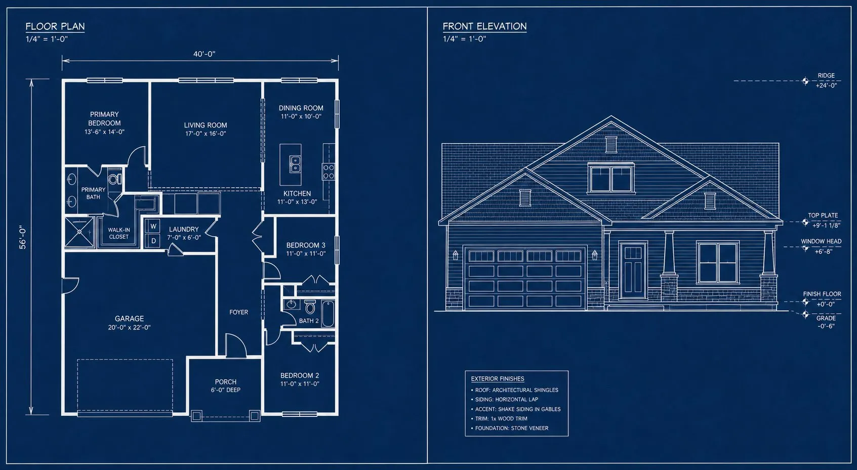
- Floor Plan (Top View) :Top-down bird's-eye view looking down from the 4-foot cut,Shows the horizontal footprint and how you walk through a space.Room connections,door swings, horizontal flow, wall lengths.
Elevation Plan (Side Wall View):Straight-on exterior or interior view looking at a vertical surface,Building height, window levels, roof pitches, exterior material finishes,Shows the vertical profile and how you look at a wall.
Floor Plans vs. Site Plans: Inside Layouts vs. Whole Property Maps
It gets even more interesting when you zoom out.
While a floor plan focuses intensely on the internal logic of a building, a site plan maps out the entire macro-environment.
Think of a site plan as a massive aerial view of the entire property lines. It reveals exactly how the building sits on the land, tracking utility connection points, driveway pathways, landscaping perimeters, setback limits, and neighboring property lines. A floor plan tells you how to arrange your kitchen counter; a site plan tells you how far your house sits from the street. You need both to achieve total structural synergy across your entire house layouts setup.
Floor Plans vs. Ceiling Plans: Looking Down vs. Looking Up
What happens when you look in the opposite direction?
A standard floor plan forces your eyes downward to inspect the ground layout, furniture paths, and wall boundaries.
But contractors need to see the roof space too.
This requires a Reflected Ceiling Plan (RCP). An RCP acts like a mirror placed on the floor, mapping out the ceiling layout looking straight up. It details complex technical elements like HVAC ventilation diffusers, recessed lighting grids, speaker paths, exposed architectural beams, and sprinkler systems. While the floor plan governs the physical path your feet walk on, the ceiling plan commands the high-tech infrastructure directly over your head.
How Floor Plans Are Used in Real Estate Marketing
Now, let’s talk about conversions.
In the premium real estate market, beautiful photos are no longer enough. High-end property buyers experience severe visual friction when trying to stitch random images together in their heads.
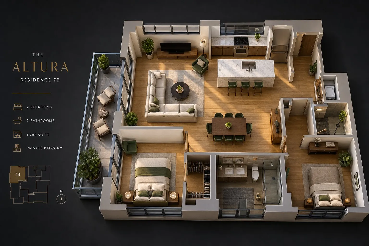
Enter the residential floor plans blueprint.
By presenting a clean, accessible layout grid directly on the listing, you activate the viewer’s imagination. They instantly stop evaluating the house as an outsider and start mentally placing their own lives inside it. They track how far the master suite sits from the kids' rooms, how the kitchen relates to the dining patio, and where their premium furniture belongs. This visual certainty dramatically drives up buyer confidence, filtering out unqualified traffic and locking in faster, higher-value listings.
How Floor Plans Help Get City Building Permits
Here is the cold, hard reality of building.
You cannot lay a single brick without explicit legal permission. Local city building departments and zoning boards look at raw ideas with absolute skepticism.
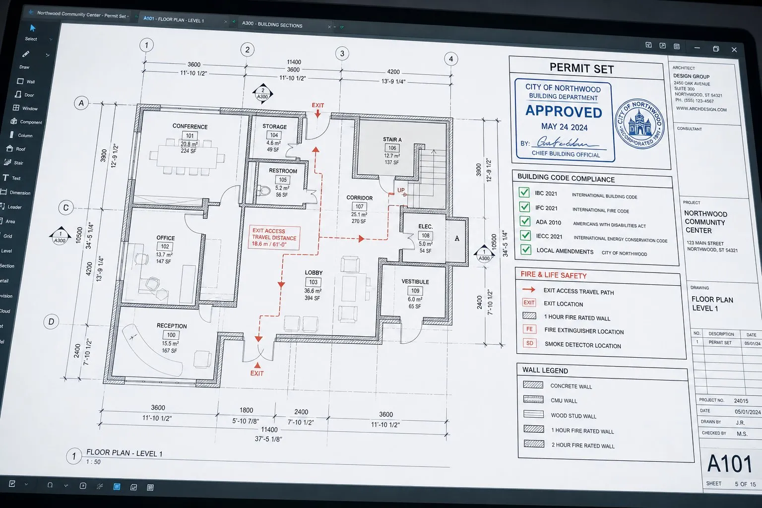
They require mathematical proof of safety.
A technical drawing acts as the primary document to satisfy local building codes and compliance requirements. It proves to city engineers that your design complies with rigorous building codes, enforces proper fire egress pathways, satisfies strict window-to-floor light ratios, and respects maximum occupancy limits. Without a precise, scaled layout, your project remains legally frozen before it even begins.
Using Layout Dimensions to Estimate Material Costs Accurately
Best of all? A meticulous plan keeps your budget from bleeding out.
Blind guesswork is the fastest way to suffer catastrophic financial overrun on a job site. If you order too much material, you burn capital; if you order too little, your project stalls completely.
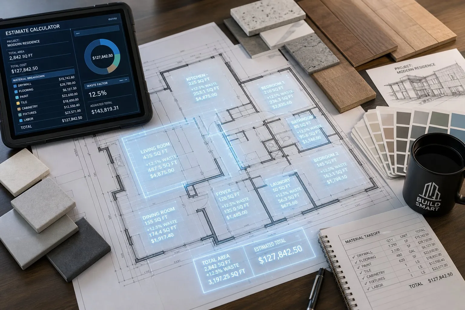
A precise layout completely solves this calculation friction. Because the plan maps out wall lengths, door schedules, and exact room areas to the millimeter, it serves as the ultimate data source for material estimation:
- Drywall & Paint: Total linear wall lengths multiplied by ceiling height yields instant, precise surface area calculations.
- Flooring: Meticulous square-footage readouts allow you to order premium tile, hardwood, or carpet down to the exact box, adding a perfect 10% safety buffer for cuts.
- Structural Headers & Framework: Door and window counts tell your framing team exactly how many studs and structural lumber pieces are required.
By deploying an advanced digital floor plan maker, you transform your architectural layout into a highly accurate cost calculator—giving you absolute certainty over your budget, your timeline, and your ultimate spatial vision.Now that you have your architectural floor plan locked in, learn how to style your space in our Ultimate Guide to Home Design
Frequently Asked Questions
What is the absolute easiest way to draw a floor plan for a beginner?
The fastest, most friction-free method is using a dedicated online floor plan maker. Rather than fighting manual graph paper or high-end CAD grids, beginner-friendly tools allow you to drag and drop structural walls, snap to exact dimensions, and automatically verify spatial flow without requiring technical architectural training.
Can an AI floor plan generator create real, buildable construction blueprints?
An AI floor plan generator is exceptional for rapid spatial prototyping, architectural text-to-layout synthesis, and exploring creative room proximity options instantly. However, for legal building permits and construction execution, the AI output must be reviewed, scaled, and detailed inside traditional architectural software or verified by a licensed engineer to ensure compliance with local building codes.
What is the difference between a 2D floor plan and a 3D floor plan layout?
A 2D floor plan is a strictly flat, technical layout map viewed from a top-down perspective that details structural dimensions, wall thicknesses, and door swings. A 3D floor plan extrudes those flat lines upward along the vertical Z-axis, transforming the architectural layout into a realistic visual model complete with textures, lighting, and depth to help clients easily visualize structural massing.


